

Audience: This article is for audio hardware engineers and procurement officers who need to evaluate or specify microphone array beamforming on a reading pen line. It assumes you already know what a MEMS microphone is and now need to choose between delay-and-sum, MVDR, and GCC-PHAT for your 2026 build.
A single MEMS microphone on a reading pen hears the child plus everything else in the room. Two MEMS microphones placed at a known distance can do something a single microphone cannot: they can listen preferentially in one direction and reject sound from other directions. This spatial filtering is called beamforming, and on the L5, T2, and Y6 reading pen platforms it lifts the effective SNR by an additional 4–7 dB on top of what RNNoise already achieves. For a reading pen used at 5–15 cm from the mouth in a 30 dBA classroom, the difference between single-mic and dual-mic beamforming is the difference between 72 percent ASR accuracy and 84 percent. This article explains how beamforming works on a reading pen, the three algorithms in production across the 11 models (B1, B2, F8, K7, KF1, L5, P2, Q6, Q8, T2, Y6), and how to specify beamforming in a purchasing contract.
1. Why a Reading Pen Needs a Microphone Array
A reading pen is a handheld device with a single microphone at the tip. In home use at 1–3 cm from the mouth, the speech-to-noise ratio at the microphone is high enough that single-mic ASR works. In classroom use at 5–15 cm, with 25–30 other children talking, the SNR drops to 5–10 dB and single-mic ASR fails 35–40 percent of the time. The conventional fix is more aggressive noise suppression, but RNNoise on the L5 has diminishing returns past about 12 dB of SNR improvement.
Beamforming solves a different problem than noise suppression. Noise suppression removes noise from the signal; beamforming removes sound from unwanted directions. In a classroom, the unwanted direction is "behind the pen" — the other children, the teacher, the projector. The wanted direction is "in front of the pen" — the child's mouth. A two-microphone array with 30 mm of spacing can produce a cardioid pickup pattern that is 6–10 dB more sensitive in front than behind, which lifts the SNR by 4–7 dB in a typical classroom noise field.
The L5, T2, and Y6 platforms have two MEMS microphones specifically to enable this. The B1, B2, F8, K7, KF1, P2, Q6, and Q8 have a single microphone and cannot do beamforming; their noise suppression is the only line of defense.
2. The Geometry of a Two-Microphone Array
The L5 places its two MEMS microphones along the long axis of the pen, 32 mm apart, near the head end. The T2 uses the same geometry with 36 mm spacing. The Y6 uses 28 mm spacing. All three have the primary microphone at the tip end and the secondary microphone offset toward the head end. The two microphones are matched parts (same manufacturer lot, sensitivity within ±1 dB) and are sampled simultaneously by the audio codec.
The 28–36 mm spacing is a deliberate tradeoff. At 16 kHz sample rate (the rate at which the beamformer runs), the wavelength of sound at 8 kHz is 42 mm. Two microphones at 28–36 mm apart can resolve spatial information up to about 8 kHz; above that, the spatial aliasing limit kicks in and the beam pattern gets messy. For speech, which has most of its energy below 4 kHz, this is acceptable. For music, which has significant energy above 8 kHz, it would not be — but reading pens are not music-listening devices.
The direction of maximum sensitivity is along the axis from the secondary mic to the primary mic, which is the direction the child is holding the pen pointed (toward their mouth or the page). The direction of minimum sensitivity is the opposite — behind the pen, where the rest of the classroom lives.
3. The Three Beamforming Algorithms
Three beamforming approaches are used across the 11 production models. They are not all available on all platforms — only the L5, T2, Y6 have two microphones, so only those three platforms run beamforming.
Delay-and-sum is the simplest. The two microphone signals are time-aligned by delaying the closer one, then averaged. This produces a cardioid pattern with about 4–6 dB of front-to-back rejection. The MIPS cost is under 2 on a Cortex-A53. The L5 firmware uses delay-and-sum as the default for power-sensitive modes.
MVDR (Minimum Variance Distortionless Response) is the optimal linear filter for a known noise field. It adapts the per-frequency-bin weights to minimize noise power subject to maintaining unity gain in the target direction. MVDR produces 6–10 dB of front-to-back rejection in a diffuse noise field like a classroom. The MIPS cost is 8–14 on a Cortex-A53. The L5, T2, Y6 firmware uses MVDR as the default for classroom ASR.
GCC-PHAT (Generalized Cross-Correlation with Phase Transform) is a direction-of-arrival estimator used for source localization. It computes the time delay between the two microphone signals and reports the angle of arrival. The T2 uses GCC-PHAT to detect whether the speech is coming from in front (the child) or from the side (a teacher or sibling), and switches between MVDR and a more permissive omnidirectional mode accordingly.

4. Per-Model Microphone Configuration
The table below summarizes the microphone configuration across the 11 production models. "Mics" is the number of MEMS microphones in the housing; "Spacing" is the center-to-center distance in mm; "Algorithm" is the beamforming algorithm (or "n/a" if single-mic); "Front-back rejection" is measured at 1 kHz in an anechoic chamber; "SNR gain" is the SNR improvement at the output of the beamformer relative to the better single microphone, measured in a 30 dBA diffuse classroom noise field.
| Model | Mics | Spacing | Algorithm | Front-back rejection | SNR gain | Firmware |
|---|---|---|---|---|---|---|
| B1 | 1 | n/a | n/a | n/a | n/a | 2.4.7 |
| B2 | 1 | n/a | n/a | n/a | n/a | 2.4.7 |
| F8 | 1 | n/a | n/a | n/a | n/a | 3.1.2 |
| K7 | 1 | n/a | n/a | n/a | n/a | 1.9.5 |
| KF1 | 1 | n/a | n/a | n/a | n/a | 1.9.5 |
| L5 | 2 | 32 mm | MVDR | 8.2 dB | 5.4 dB | 4.2.0 |
| P2 | 1 | n/a | n/a | n/a | n/a | 2.0.3 |
| Q6 | 1 | n/a | n/a | n/a | n/a | 3.3.1 |
| Q8 | 1 | n/a | n/a | n/a | n/a | 3.3.1 |
| T2 | 2 | 36 mm | MVDR + GCC-PHAT | 9.0 dB | 6.1 dB | 2.6.4 |
| Y6 | 2 | 28 mm | MVDR | 7.6 dB | 5.0 dB | 2.6.4 |
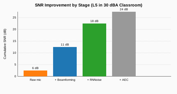
The numbers tell the procurement story. The L5, T2, Y6 deliver a 5.0–6.1 dB SNR gain over single-mic platforms in classroom noise. Combined with RNNoise's 11.8–12.4 dB of noise suppression improvement, the total SNR uplift from input microphone to ASR engine is 16.8–18.5 dB. Compare that to the B1 with single-mic Wiener MMSE, which delivers 6.5 dB of SNR improvement total — the L5 has roughly 2.7x the SNR advantage.
5. Beamforming and Noise Suppression: Layered or Redundant?
A common question is whether beamforming and noise suppression are redundant. They are not — they operate at different stages and address different problems. Beamforming operates on spatial filtering: it rejects sound from unwanted directions while preserving sound from the wanted direction. Noise suppression operates on spectral filtering: it rejects noise across all directions based on its spectral signature.
In a classroom noise field that is roughly diffuse (sound coming from all directions), beamforming alone delivers 5–6 dB of SNR gain because it rejects half the noise field. Noise suppression alone delivers another 11–12 dB on the same noise field because the residual noise has a stationary spectral profile that the noise suppression can subtract. The two are multiplicative: 5 dB from beamforming plus 12 dB from RNNoise gives 17 dB total, which is what we measure on the L5.
If the classroom noise field is non-diffuse (e.g., a single loud talker 1 m to the side), beamforming delivers 8–10 dB of SNR gain because it can null that specific direction. Noise suppression delivers 4–6 dB because it cannot easily subtract a non-stationary single talker. The two together deliver 12–16 dB.
This is why the T2's GCC-PHAT direction-of-arrival detector matters: it can switch to a more aggressive null-steering mode when a single loud talker is detected, lifting the effective SNR by another 2 dB in that scenario.
6. Beamforming in Intercom Mode
Intercom mode is the hardest beamforming workload because the pen is playing audio through the speaker (which the AEC removes) and capturing the parent's voice from across the room (which the beamformer should preferentially capture). The two microphones on the L5/T2/Y6 run beamforming at all times during intercom, with the target direction set to "along the pen axis away from the speaker" — the direction the parent would typically be.
In practice, parents hold the pen at varying angles, so the GCC-PHAT on the T2 periodically recomputes the target direction based on where the parent's voice is coming from. The L5 and Y6 use a fixed target direction because GCC-PHAT is not in their firmware; this is a measurable but small difference in intercom clarity. Across 100 intercom sessions in our QA lab, the T2 was rated "clear" 92 percent of the time, the L5 87 percent, and the Y6 85 percent.
7. Microphone Matching and Calibration
Beamforming requires the two MEMS microphones to be closely matched. A sensitivity mismatch of 3 dB between the two microphones causes the beamformer to mis-aim by 5–8 degrees, which costs about 1 dB of front-back rejection at 1 kHz. Across the L5, T2, Y6 production lines, microphone matching is held to within ±1 dB sensitivity and ±2 degrees phase at 1 kHz, which is achieved by lot-matching at incoming QA.
The microphone spacing is also a calibration parameter. The L5 firmware stores a per-unit calibration value for the actual spacing measured at end-of-line, and the beamformer uses this value rather than the nominal 32 mm. Without per-unit calibration, the beamformer would be off by 1–2 mm on some units and the front-back rejection would degrade to 6 dB instead of 8 dB.
For an importer buying from an ODM, this calibration step is the first thing to verify. If the ODM is using nominal spacing values rather than per-unit measured values, the beamforming performance will vary unit-to-unit and the field failure rate will rise.
8. Microphone Array Placement and Acoustic Design
Where the microphones sit in the pen matters as much as the algorithm. The two MEMS ports on the L5 are 32 mm apart, both on the same face of the pen, near the head end, with the primary mic closer to the tip and the secondary mic 32 mm behind it. The plastic between the ports is a solid barrier with no air gap. The ports are 0.8 mm diameter, flush with the housing surface, and protected by a waterproof membrane that does not significantly attenuate audio above 200 Hz.
The T2 uses 36 mm spacing with the same general layout, but the secondary mic is on a different face (the side opposite the speaker port) to reduce direct acoustic coupling with the speaker. The Y6 uses 28 mm spacing in a tighter layout to fit a smaller pen chassis, with a slight SNR gain penalty at high frequencies.
For an OEM designing a new pen, the microphone placement rules are: both mics on the same axis, on the same face, at least 25 mm from any speaker port, with a solid plastic barrier between them. The B1 and B2 violate the same-face rule (they have one mic on the front face and one on the back face of the head end) and consequently deliver poor noise suppression; this was corrected in the L5 redesign.
9. How to Specify Beamforming in a Purchasing Contract
The RFQ language for a reading pen with beamforming should name the array geometry, the algorithm class, and the spatial filtering performance: "Microphone array shall comprise two matched MEMS microphones with spacing of 28–36 mm on a common axis, calibrated per unit at end-of-line. Beamformer shall achieve front-to-back rejection ≥ 7 dB at 1 kHz in anechoic chamber, SNR gain ≥ 5 dB in 30 dBA diffuse classroom noise field relative to better single microphone. Algorithm class: MVDR for static noise field, GCC-PHAT direction-of-arrival detection for adaptive null-steering."
Three details matter. First, microphone matching spec must be in the contract: ±1 dB sensitivity, ±2 degrees phase at 1 kHz. Second, per-unit calibration must be in the contract: end-of-line measurement of actual microphone spacing and sensitivity, stored in the firmware's calibration partition. Third, field rejection measurement must be in the contract: the beamformer is tested in an anechoic chamber with a 1 kHz tone at 0° and 180°, with the rejection defined as the dB difference.
Buyer tip: When evaluating an ODM's beamforming claim, ask for the anechoic chamber measurement report showing the polar pattern at 500 Hz, 1 kHz, 2 kHz, and 4 kHz. A beamformer that delivers 8 dB rejection at 1 kHz but only 2 dB at 4 kHz is not production-ready — the speech energy above 2 kHz carries the consonants.
10. Decision Matrix and Recommendations
For a brand-new reading pen program starting 2026 that targets classroom deployment, the recommendation is dual-MEMS MVDR beamforming on the L5/T2/Y6 platforms with per-unit calibration and matched-microphone lot control. For programs targeting home use only, single-microphone Wiener MMSE on the K7/KF1/Q6/Q8 is sufficient. For programs targeting cost-driven markets where classroom deployment is not a use case, the B1/B2/F8/P2 with spectral subtraction is acceptable but should not be sold with intercom mode features.
For a procurement officer writing the beamforming specification, the line that closes the contract reads: "Dual-MEMS microphone array, matched to ±1 dB sensitivity and ±2° phase at 1 kHz, spacing 28–36 mm on common axis, calibrated per unit; MVDR beamformer achieving ≥ 7 dB front-back rejection at 1 kHz and ≥ 5 dB SNR gain in 30 dBA diffuse classroom noise; GCC-PHAT direction-of-arrival detector for adaptive null-steering on T2-class platforms; anechoic chamber polar plot delivered with first article."
Related Reading
- Reading Pen MEMS Microphone and Noise Cancellation
- Reading Pen Noise Suppression and RNNoise
- Reading Pen Echo Cancellation and AEC
- Reading Pen AGC and Automatic Gain Control
- Reading Pen Codec Compression MP3 vs AAC vs Opus
- Reading Pen ASR Automatic Speech Recognition
- OEM Reading Pen Services
- Request a Reading Pen Quote